Does Your Crank Grinder Need A Checkup?


When crankshaft grinders start getting old and not performing like they did when new there are some simple checks that most shops can make to figure out what is wrong. Since most crank grinders have chucks we will concentrate on those machines.

Grinders that only use centers can use the same procedures for “spindle bearing alignment” except the test bars will have to be machined to fit where the centers go in the machine before they can be ground for testing.

It’s a very common assumption to think that out of round grinding is caused by wear in the chucks. While chucks can be a problem, there can be other issues with the grinder. So before you make a sizeable investment in a pair of chucks that you might not need, you can go through some easy checks to see what is really causing your problems.

Because you are going to do quite a number of measurements, be certain to write the numbers down. After the checks are complete if you talk to someone that repairs machines and you want to give them an accurate picture of what you discovered. Be certain to clean under the head and tailstock and remove any nicks and burrs from the table before starting!
Step 1: Checking Your Chucks

Step 1: Checking Your Chucks

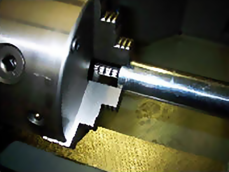
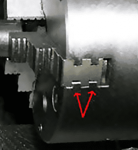
We will start by checking the chucks. The first thing you need to look at is to see if you have double groove chucks on your machine. My experience is that a single groove chuck will not work properly on a crank grinder. I’ve worked with quality brands of single groove chucks to try and reduce the cost of crank grinding and came away convinced that double grooved chucks are the only way to have a good grinding machine.

Now, just because you have double groove chucks doesn’t mean that they are good chucks for crank grinding. Also keep in mind that when I say a “good grinding” machine, I mean one that you don’t have to pussy foot around with the steady rest or “lean” on the steady rest at the right time to get the journal round. Mild pressure on the steady rest shoes is all you should have to apply to get a round journal. Now that I’ve said that, you probably know that some crankshafts are just plain ornery and will not settle in without some extra encouragement.

Step 1: Checking Your Chucks

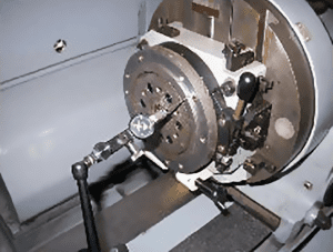
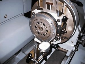
The first step is to remove both chucks to check the runout of the faceplate flange or “step” that centers the chucks and the runout of the face where the chuck bolts to. Both these areas should have no more than a .001″ runout when you rotate the faceplate. You must have the locking pins for the head and tailstock engaged when rotating the faceplate because you are checking the chuck faceplate runout only, not the rotation of the head or tailstock.

Assuming the runout is OK and the chuck has a good fit for centering on the flange, the next step is to see how far off center the chuck jaws are when they are tightened. You must clamp a test bar in each chunk for this operation. Be certain the test bars contact all of the teeth of the jaws. For this you can use two pieces of bar stock from 1″ to 3″ in diameter and at least 10″ long so that you have about 8″ sticking out of each chuck after clamping. It is important to check a chuck in this manner to see if the chuck causes the test bar not to center or that it makes the test bar point away from the center after clamping. If you cannot easily get bar stock, Black Hills Tool & Manufacturing has test bar stock for sale.

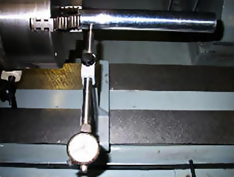
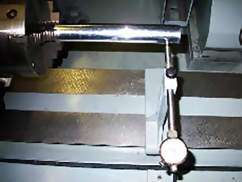
First, check the runout of the test bar as close as possible to the chuck jaws with a dial indicator. Rotate the chucks and faceplates with the head and tailstock locking pins engaged. Then move the dial indicator toward the end of the test bar and rotate the chucks again. Perfect would be no more than a .001″ runout in either location, but you will most likely see .002″-.003″ close to the chuck and up to about .005″ at the end of the test bar. If you have a shorter or longer test bar, you will have to add or subtract for the change in distance at the far end measurement.

Step 1: Checking Your Chucks

If your numbers fall outside the ideal ones you could possibly need chucks. My suggestion is to talk to your machine repair expert or companies listed in the sidebar.

Trying to repair chucks by replacing jaws or scrolls is money wasted. The tolerances you need to hold on modern cranks are far more stringent than they used to be, and anything you do to “patch” a chuck could only be a short term fix, if any fix at all.

Step 2: Table Check
Step 2: Table Check

Step 2: Table Check

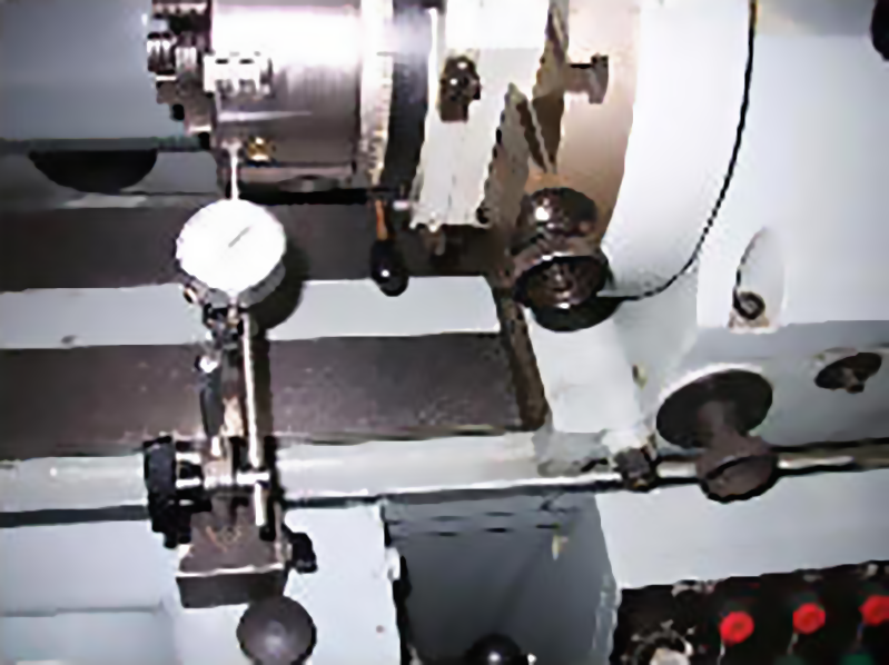
Next we want to check the table for wear. You can attach an indicator to the grinding wheel, grinding wheel spindle housing or the gearbox on the front of the machine.

Place the indicator against the top of the table in the front and move the table in the front and move the table left to right so the dial indicator passes from unworn over the normally used worn area to see how much wear has been created from moving the tailstock back and forth. Then place the indicator over the back part of the table and run the check again. The most critical check is the front edge of the table. Place the indicator on the front edge and run the table back and forth. Remember to write all these numbers down for future reference.

Step 3: Tailstock Wear Check

Step 3: Tailstock Wear Check

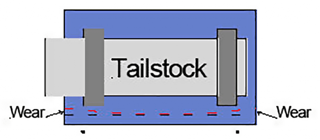
Now, place the tailstock in an unworn area of the table. Position an indicator against the chuck to check the tailstock for rocking. Tighten one of the tailstock hold both bolts only and zero the indicator. Loosen that bolt and tighten the other one to see if the indicator moves at all. If it does, you have “rocking” wear in the tailstock where it contacts the front of the table. That wear needs to be corrected before any meaningful alignment measurements can be taken.

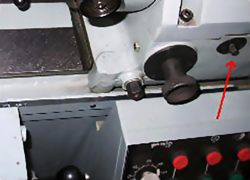
Even if you have an air floated head and tailstock and have always cleaned them carefully before moving, you can have this type of wear. The cause is the force created when you offset the chucks and counterweights for grinding rod throws. Even though you do not see any movement when the machine is running, it is constantly trying to rock the head and tailstock back and forth. It is also common to have the hold down bolts get rusty so they do not apply enough pressure to hold the head or tailstock solid against the table, which will aggravate the problem. Cleaning and lubricating the hold down bolts is important to help prevent this from happening.

Step 4: Checking For Taper

Step 4: Checking For Taper

There cannot be any tailstock rocking in order to accurately check the machine for taper with test bars. We still don’t know about the alignment of the head and tailstock but we have to get the tailstock the same distance from the grinding wheel as the headstock so our measurements in the next step will be correct.

At this point, the easiest way to check taper is by using the test bars clamped in the chucks with all the teeth are making contact. Zero the test bars with an indicator as close to both chucks as you can using the machine’s stroke and cross slide adjustments.

Be certain the tailstock is tightened down in an unworn area of the table before you start making adjustments.

With a dial indicator attached to the grinding wheel (see Checking Spindle Alignment about attaching a dial indicator to the grinding wheel), bring it in to where you zeroed the test bar on the head stock. Rotate the grinding wheel to find the high point of the test bar and adjust the indicator to zero. Rotate the grinding wheel slightly to clear the test bar and move the indicator over to the test bar in the tailstock. Check the test bar position in the same spot you zeroed it in by slowly moving the indicator up and down to find the high spot.

If the indicator is not reading zero you have to move the tailstock taper adjustment to get a zero reading. When you move the tailstock in or out, the height of the tailstock could change, so be certain to rock the grinding wheel slightly to know that you are on the high point of the test bar.

Step 5: Checking Machine Alignment

Step 5: Checking Machine Alignment

Now that you have the taper set, let’s understand the important alignment concepts for your machine. The alignment that makes a crank grinder work properly is based off an imaginary line that goes through the center of the bearings in the head and tailstock. Since you cannot see this line, we need to establish something that we can measure to find out if everything is in the right place. There are two methods used to create points where you can measure the spindle bearing angles. Either one can be used successfully but my choice for your check is to use the first method.

Method 1: Not Grinding Test Bars

Method 1: Not Grinding Test Bars

Be certain the tailstock is on an unworn part of the table so you will be checking spindle bearing alignment and not table wear. Tighten the head and tailstock up just like you were going to grind a crankshaft. Put the test bars in each chuck, but unlike the first tests where you needed to have all the teeth contacting the test bars, grip the test bars with only one tooth of the jaws.

Use your machine’s setup indicator to “zero” the test bars. You will be going from one end of the test bars to the other many times and it is a lot easier moving the setup indicator than moving the table back and forth.

With the locking pins released, rotate the chuck and spindle together because we are now looking for the imaginary center line of the spindle bearings. Start by getting the runout of the test bar to “0” next to the chuck. Use the stroke and cross slide adjustments on your machine for this. Then, move the indicator out at least 8″ on the test bar and “bump” the test bar by hand or with a soft mallet to get it to “0”. When you bump the test bar like that, it will most likely change the reading close to the chuck, so go back and forth until you bet both readings less than .0005″. Put a magic marker line where you measure so you can go back to the exact same spot each time.

Zero the test bar in the tailstock the same way. The problem with this type of check is that the slightest bump of the test bar can move it, so be careful! Check the test bars for runout after you check the spindle alignment to be certain they did not move.

Method 1: Not Grinding Test Bars

Checking Spindle Alignment

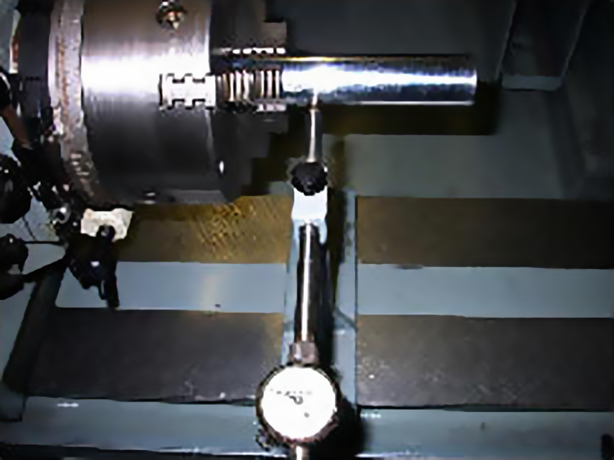
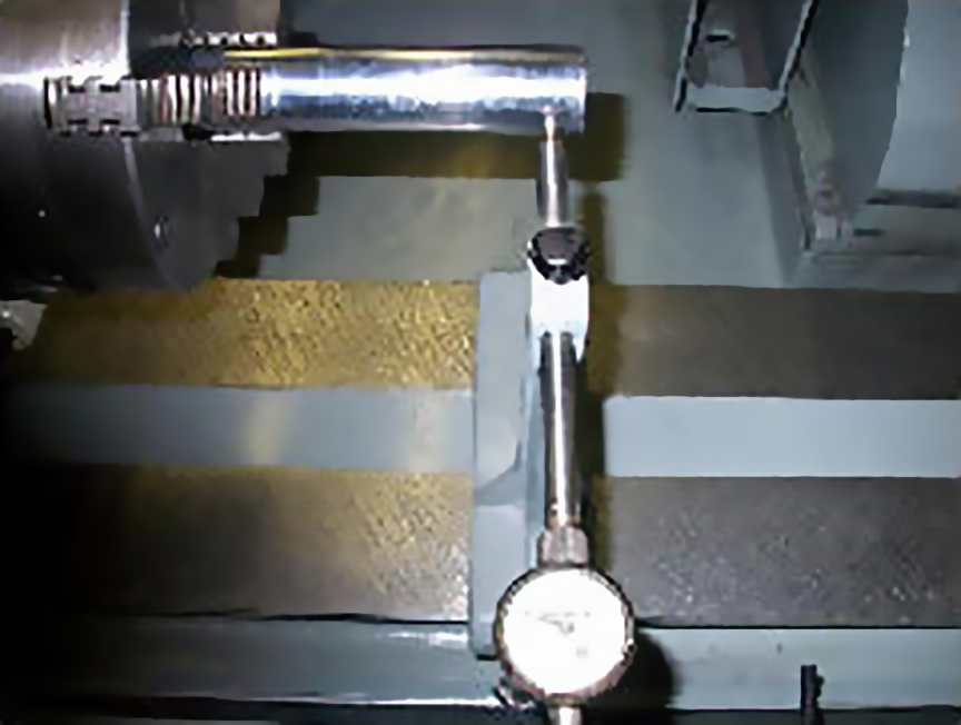
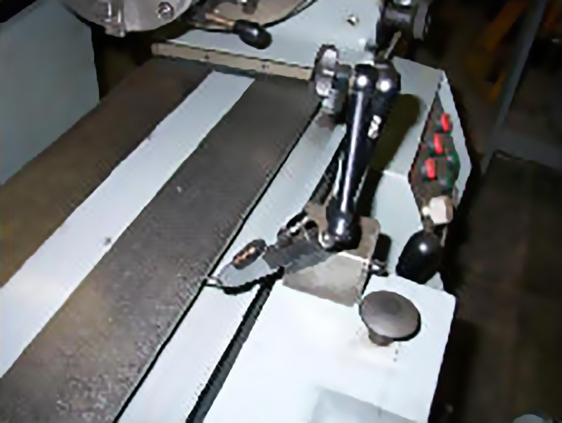
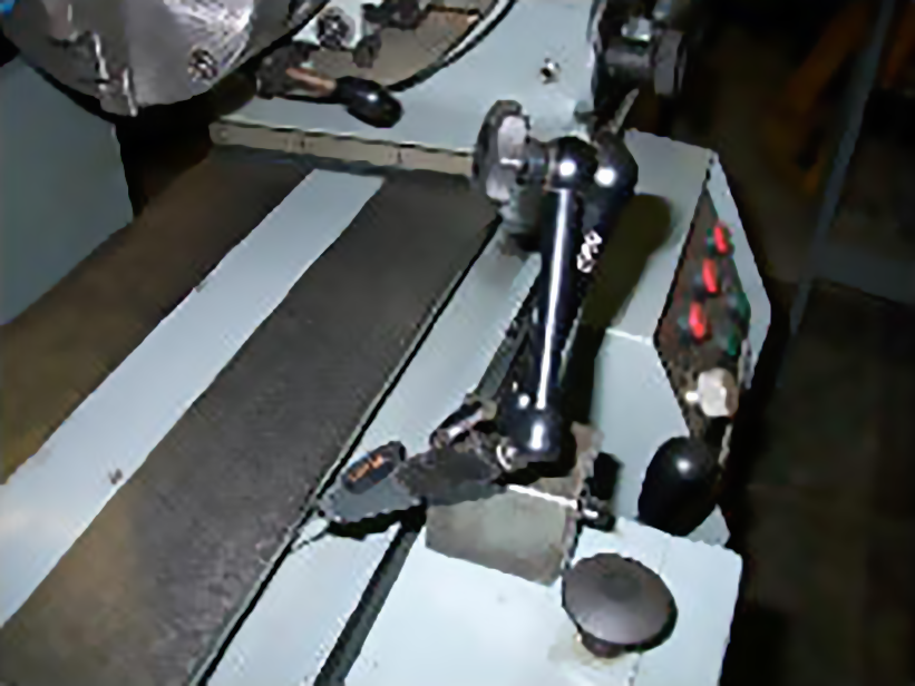
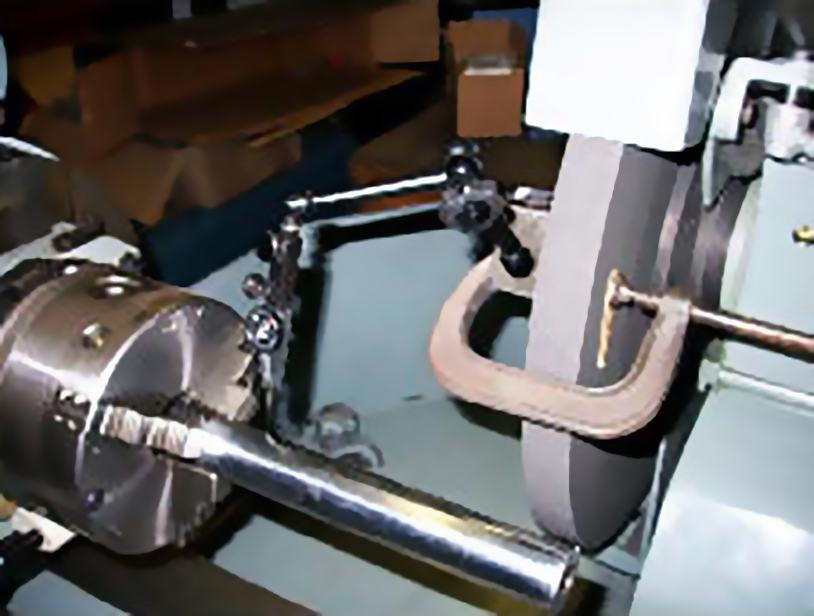
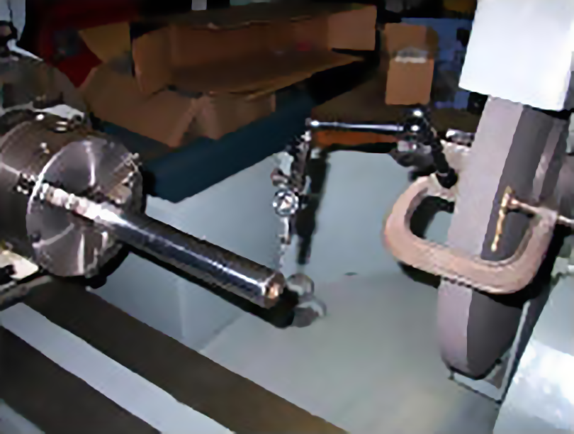
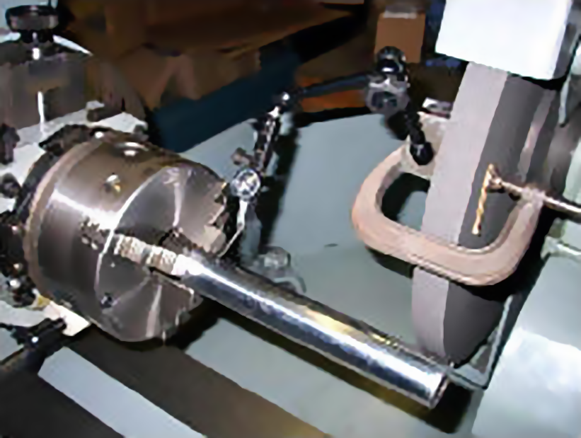
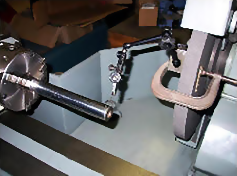
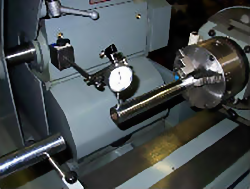
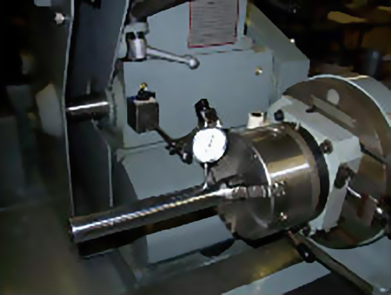
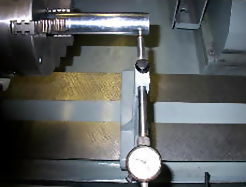
OK, now that all that work is done and you have measuring points, you can find out where that imaginary line is between the head and tailstock. It can be done two different ways. You can attach your indicator to the grinding wheel or to the wheelhead spindle housing with a magnetic base. Use whatever you have available for indicators and clamping devices. Notice that in the pictures of the indicator attached to the grinding wheel there are broken tongue depressors placed between the magnetic base, “C” clamp and wheel. Paint sticks also work very well to prevent damage to the grinding wheel.

When attached to the grinding wheel, bring the wheelhead in until the dial indicator contacts the back of the test bar at the left hand measuring point. Rotate the grinding wheel slightly up and down so the indicator finds the high point of the round surface, then use the infeed wheel to “0” the indicator.

Checking Spindle Alignment

Now rotate the grinding wheel so the indicator is just clear of the ground surface. Move the indicator to the next measuring point and slowly rotate the grinding wheel until the indicator reaches the high point. Record that number, + or – of the zero reading you had set on the indicator at the first measuring point.

Move to the same measuring points on the test bar in the tailstock and check each one by slowly rotating the grinding wheel to find the high point and then record the number.

During the zeroing and the checking process, extreme caution has to be used so that nothing touches the test bars to move them out of alignment! Even a slight bump can cause the alignment to change.

To be certain nothing changed during your measuring sequence, return to the first measuring point you checked to be certain the indicator reads “0”. If it does not, and you need to re-zero the indicator, check the test bars for runout and check all the measuring points again so you have accurate readings.

The ideal numbers using the left to right sequence would be 0, -001, -001, 0. The reason you want the bars pointing to the operator (-.001) is that when you touch a crank with the steady rest top shoe during grinding, you will push it toward the centerline of the bearings.

Now, change the indicator so it touches the top of the left hand measuring point. Use a combination of rotating the grinding wheel and the infeed handwheel to move the indicator back and forth over the top of the measuring point, find the high point, and then “0” the indicator.

Checking Spindle Alignment

Use the infeed wheel to move the indicator back far enough to clear the test bar. Then go in the same sequence to the right to check each measuring point. Use the infeed wheel to advance the indicator over the top of each measuring point to find the high point.

The ideal numbers using this sequence would be the same 0, -001, -001, 0. We want the center down so when the bottom shoe of the steady rest is used, it moves the crankshaft up toward the center line of the bearings.

It would not surprise me if you saw numbers like 0, -001, +015, 0 for the side measurement and 0, -001, -015 for the top measurement. The wear will usually occur in the tailstock, and it normally points the test bar back toward the grinding wheel and down.

If you use a magnetic base indicator on the grinding wheel spindle housing, follow the same sequence for contacting the measuring points. Since you cannot rotate the grinding wheel “zeroing” the indicator is different but the end result for your numbers will be the same.

Checking Spindle Alignment

When your machine is far away from the ideal numbers, it can be very difficult to get a round journal when grinding. since normal wear will move the tailstock toward the wheelhead and point the test bar down quite a bit, top shoe steady rest pressure will push the crank further away from the bearing centerline. Heavy bottom shoe pressure might help bring it up toward the centerline of the bearings.

Method 2: Grinding Test Bars

Method 2: Grinding Test Bars

Note: If your machine is able to grind on centers only, you will have to machine one end of each test bar to fit where the centers go in order to grind them for the spindle bearing alignment check.

With the test bars installed all the way into the chucks as you did during the chuck checking, loosen the locking pins so the head and tailstock can rotate. Center each test bar using your setup indicator. Use the stroke and cross slide adjustments of the machine to make adjustments.

Because you will not be using a steady rest, it is best to have minimal runout at the end of the test bars to have less problems grinding them.

It doesn’t matter what width wheel you have in the machine, but if you have a choice, use the narrowest one that you grind steel shafts with. That should work the best with a course dress on the wheel.

Start grinding by moving the wheel into the test bar close to the chuck where the most runout of the test bars is. Use caution when grinding because you are grinding wheel and you cannot use the steady rest. You need to slowly plunge grind until you have the test bar round. Doesn’t matter what size you make it, just carefully grind the test bar round in the one spot. Zero your “Arnold” gauge on that ground surface so you know what size it is.

After the first area is ground move the wheel to the end of that test bar and carefully plunge grind it without a steady rest to the exact same size that the first one is, again using the “Arnold” gauge that you have set to get the same diameter.

Now if you are going to grind the tailstock first, you might notice that you have to rotate the tailstock chuck by hand. This can be tricky and has to be done with 2 people, one rotating the tailstock and the other doing the grinding.

CAUTION! Be careful that your human “motor” does not get wrapped up in the machine. You need someone with patience and good hand-to-eye coordination to prevent an accident when rotating the tailstock chuck for grinding.

The next step is to move to the other test bar and repeat the same procedure. Keep in mind that what you are trying to do is create 4 ground surfaces that are the same diameter. These same diameter ground surfaces are rotating on the centerline of the bearings in the head and tailstock. Now we can use these ground surfaces to see where the centerline of the bearings are.

During the grinding and after the 4 surfaces are ground, extreme caution has to be used so that nothing touches the test bars to move them out of alignment! Even a slight bump can cause the alignment to change.

Use the same procedures described in the previous “Spindle Alignment Checking” section to check alignment using the surfaces on the test bars you have just ground. If your numbers are way off, my suggestion is to consult with your trusted machine rebuilding person or companies listed in the sidebar.